With the term SSI, we refer to a wide variety of sensors that use the SSI interface to transmit data. These sensors are typically absolute encoders and can be single-turn or multi-turn, with varying frame lengths and operating frequencies. Additionally, the hardware layer may differ between models.
Due to these variations, it is essential to carefully review the datasheet of each sensor before determining whether it is supported. This article outlines the supported characteristics of SSI sensors for the F3 and G4 product families.
Considerations for Both Prev. Gen (F3) and New Gen (RoboG4) products
For both product families, the hardware layer must be RS-422. SSI sensors using RS-422 will have the following connections:
- Clock +
- Clock -
- Data +
- Data -


Any other sensors that have different pinout are not supported.
Additionally, the encoding must be pure binary. Encoding types such as Gray code, offset binary, or others are not supported.
 | Only pure binary encoding is supported. Encoding types such as Gray code or offset binary are not compatible with G4 products. |
Old Gen (F3) products (e.g. FBL2360T, GDC3660T etc.)
Resolution
F3 products support only single turn sensors up to 16 bits.
Data Frame
The sensor's datasheet provides the structure of the data frame. When examining the frame, it is important that no bits unrelated to angle information—such as status bits—precede the actual data bits. The motor drive, drives the sensor using the clock signal and reads data up to the expected number of bits. If irrelevant bits come before the angle data, the readings will be affected.
In the example below, the status bits appear first, which interferes with the angle data:

However, if status bits are present but appear at the end of the frame, they will not interfere with the angle readings, as the motor drive can be configured to read only the required initial bits.
In the example below, a 10-bit SSI sensor includes 8 data bits and 2 status bits. The drive can be configured to receive only the angle data, ensuring accurate readings.
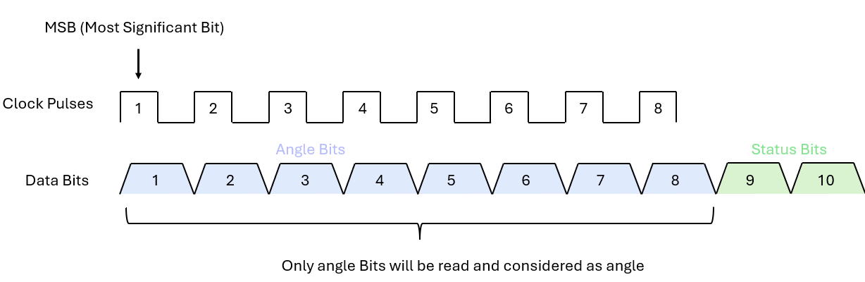
| When reviewing the sensor datasheet, ensure that no dummy bits—such as status bits—precede the angle data. |
Clock frequency
The motor drive requests the sensor angle at 16 kHz (every 65.2 µs). During this time, it provides the clock signal and receives the sensor data bits.

The clock frequency must be configured fast enough to ensure all angle bits are received before the next request. In the example below, the clock frequency is too low, so not all 10 bits can be received in time.

Since communication frequency is 16 KHz, we want the SSI sensors supported frequencies to be higher than 16Khz multiplied by the total number of angle bits:
Fmax > 16 KHz * number of angle bits |
Also this frequency must be on the range of the supported frequencies by Roboteq controllers, that for F3 products are 280 ~ 2250 KHz.

| Supported Clock Frequency for F3 products is between 280 to 2250 KHz. |
New Gen (Robo G4) products (e.g. FBLG2360T, GDCG3660T etc.)
Resolution
G4 products support both single-turn and multi-turn encoders with resolutions up to 47 bits. One important consideration is that the Feedback parameter is of type S32, meaning that if the sensor resolution exceeds this limit, the full range cannot be utilized. In such cases, the multi-turn or single-turn resolution should be reduced by configuring the controller to read fewer bits from the angle data.
| Sensors with angle resolution higher than 32 bits will be limited by the 32 b Feedback parameter |
Data Frame
In the G4 implementation, users can identify both multi-turn and single-turn angle data within the frame. Essentially, all data frame formats are supported, as long as the combined number of single-turn and multi-turn bits does not exceed 47.

Clock frequency
The motor drive requests the sensor angle at 16 kHz (every 65.2 µs). During this time, it provides the clock signal and receives the sensor data bits.

The clock frequency must be configured fast enough to ensure all angle bits are received before the next request. In the example below, the clock frequency is too low, so not all 10 bits can be received in time.

Since communication frequency is 16 KHz, we want the SSI sensors supported frequencies to be higher than 16Khz multiplied by the total number of angle bits:
Fmax > 16 KHz * number of angle bits |
Also this frequency must be on the range of the supported frequencies by Roboteq controllers, that for Robo G4 products are 680 ~ 10800 KHz.
 | Supported Clock Frequency for F3 products is between 680 to 10800 KHz. |
