← 3.2.1 DC - Closed Loop - Torque v 1.0
3.2.3 DC - Closed Loop - Count Position v 1.0 →
3.2.4 DC- Closed Loop - Position Relative v 1.0 →
3.2.5 DC - Closed Loop - Position Tracking v 1.0 →
3.2.6 DC - Closed Loop - Speed Position v 1.0 →
Note: The Guide can be downloaded in PDF format at the end of the article.
Disclaimer and Safety Information
Disclaimer
This quick startup guide is provided as a complementary resource to the official motor drive manual and datasheets. It is not intended to be the sole source of information for proper motor drive configuration and operation. Incorrect configuration or software bugs may cause unintended behavior, including uncontrolled motor operation or runaway. Users must always conduct tests cautiously and ensure they have a reliable method to safely stop the system in such scenarios. Roboteq, the author, and related parties are not liable for any hardware damage, personal injury, or other consequences arising from the use or misuse of the information in this guide.
Safety Symbols Explanation
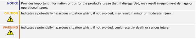
Table of Contents
1. How to Use This Guide
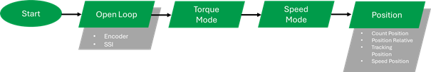
- This guide is part of a series of documents that must be followed sequentially to configure and test a Brushless DC motor. The process begins with the Open Loop configuration and continues through the sequence of documents until reaching the final target operating mode.
- For example, configuring a higher-level operating mode, such as Count Position with Hall sensors, requires completing the configuration and testing of lower-level modes, including Open, Torque and Speed modes.
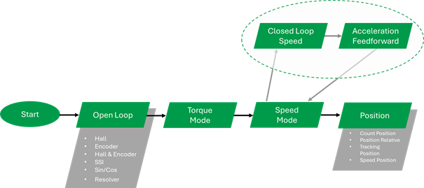
- The Speed tuning of the motor consists of two portions: Closed Loop Speed PID tuning and acceleration Feedforward control tuning, which should be configured in a sequence. First, the Closed Loop Speed will be tuned, and then it can be optimized using the acceleration feedforward control. The feedforward control step is optional.
2. Theory: Closed Loop Speed Operation
- Closed Loop Speed mode uses the feedback data to drive the motor to the desired speed
- The Loop Error, which results from subtracting the feedback from the motor command (after applying the trajectory), is used by the PID control loop to calculate the required motor power
- PID Loop uses three terms to calculated the required power as follows:

- As we will sequentially see, Speed PID output does not directly correspond to the supplied power, as Roboteq drive uses a cascaded control mode

2. Theory: Cascaded Operation
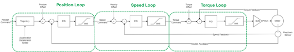
- The motor drive uses a cascaded control structure: the Position Loop controls the Speed Loop, which controls the Torque Loop, ensuring stable motor control.
- Tuning Position mode requires both Speed and Torque loops to be tuned, while Speed mode needs only the Torque loop. Torque and Open Loop modes operate independently.

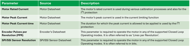
3. Required Parameters List
To complete the configuration sequence, ensure you have the following specifications readily available:
4. Configuration steps
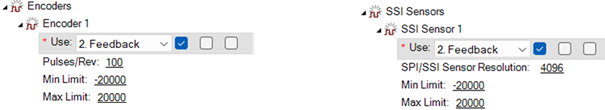
1. Configure the feedback sensor.
This action should have already been performed during the Open Loop and Torque mode configuration guides. The sensor operation and measurements should have already been evaluated there.

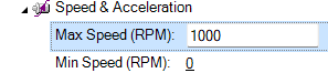
2. Configure the motor Min and Max Speed.
These are the maximum and minimum values that the motor drive is allowed to command.
3. Set the motor Acceleration/Deceleration values.
This profile will be followed by the drive when a speed command is given.

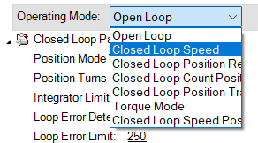
4. Set the Operating mode to Closed Loop Speed
5. Configure the Speed PID parameters.
The default values are 0 and will not result in any motor power. Start by giving a small value on the Proportional and Integral gains. Values between 0.03 to 0.3 for both P and I will make the unloaded motor to follow the given command in most cases.

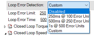
6. Temporarily disable the Loop Error detection.
At this point, the system is still untuned so Loop Error detection might be triggered
7. Navigate to the run tab and test the motor by using the slider.
Ensure that the command is reached in both directions and the speed is stable. It is not required to have a fast response at this point. If the set point is not reached, increase the I gain. Increase the P gain if the motor response is very slow.

Useful Commands
Loading the motor might result in limitations related to the available space for movement. Two useful tools that can prevent the motor from reaching the space limits are the Watchdog timer and the Console commands.
In contrast to the slider, which sends continuously motor commands to the controller over a specific time period, console commands can be used to send the motor command only once.
![]()
Console commands, in combination with the Watchdog timer, can be used to stop the motor after a specific amount of time. The watchdog will stop the motor if the command is not renewed within a defined time period.

Sending the commands through the console guarantees that the watchdog timer will expire after the configured time.
Watchdog timer will stop the motor using the configured Fault Deceleration parameter, so ensure that it has been set with the desired value:

A motor command in Speed Mode can be sent with the following syntax:
!S cc nn
where cc is the channel and nn is the desired speed in RPM.
For example, the following command will give a set point of 300 RPM in channel 1:
!S 1 300
There is also the option to send a simultaneous motor command to both channels by combining the two commands with an underscore (“_”).
For example, the following command will give a desired speed of 500 RPM to both channels:
!S 1 500_!S 2 500
Issuing a motor command for both motors can be useful in dual-channel applications like differential drive AGVs.
5. Tuning: Tuning steps
1. Give some small initial values on P and I gain:
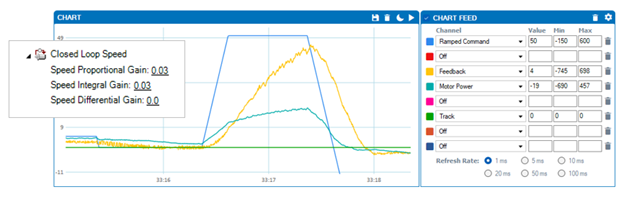
2. Adjust the P and I gains to have a smooth feedback curve resembling the one in the image below:

- This curve exhibits the characteristics of a first-order system and will result in stable behavior. At this stage, a fast response is not necessary; focus on creating a smooth feedback curve with no steady state error and overshoot.
3. To shape the response: Increase P gain for faster response; increase I gain to eliminate steady-state error.

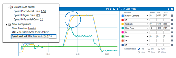
4. Multiply P and I gains by the same factor to increase the Closed Loop Speed Bandwidth:

5. If necessary, decrease the Low Pass Filter Cutoff frequency.
- When attempting to increase the bandwidth beyond a certain value, the system may exhibit vibration. This vibration may be caused by feedback fluctuations reinforcement.

- Reducing the closed-loop filter frequency enables higher Speed PID bandwidth while minimizing vibrations. However, avoid decreasing the frequency below 5 Hz, as this will cause excessive control lag.
When the Feedback follows the Ramped command in a fast and stable manner, the system can be considered tuned!
5. Tuning: Limitations and Considerations
1. PID Loop Limitations:
Minimizing the Transient Loop Error may not be always possible as the PID loop requires a certain amount of loop error to function. With lower loads, the feedback may be able to closely follow the ramped command. However, as the load increases, some transient loop error may remain. The transient system's response can be further optimized by using the Feedforward control, which will be demonstrated in the next training.

2. Motor Power Limitations:
The drive may not be able to provide efficient power or the motor may not be powerful enough to move the load. This can be determined by looking at the voltage and current during the transient response of the motor
a. Voltage limitation:
If the PWM voltage (Motor Power parameter) has reached 100% (+/- 1000 value) and the motor still cannot achieve the desired torque, speed, or acceleration, it indicates that the power demand exceeds the motor drive limits. In this case, the motor cannot follow the desired ramp, regardless of the applied voltage.

- Cases where the desired speed cannot be reached may be resolved by using field weakening. For more information, refer to the respective guide.
2. Motor Power Limitations:
The drive may not be able to provide efficient power or the motor may not be powerful enough to move the load. This can be determined by looking at the voltage and current during the transient response of the motor
b. Current limitation:
Similar to the voltage limitation scenario, the motor's acceleration may be limited if there is insufficient current available. The maximum allowed current is set via the Amps Limits parameter. This function ensures that the current does not exceed the set limit, even if the movement requires it, thereby protecting the motor and motor drive.

3. Ramped Command and Feedback considerations:
The input to the Speed loop is the error that arises when subtracting the Feedback from the motor trajectory, reported by the Ramped Command. When employing traditional PID control, the motor will not exceed the trajectory during transients. When monitoring motor performance, it's advisable to examine the Ramped command instead of the motor command, as this disregards the configured acceleration profile.

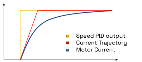
4. Motor current Slew Rate:
The output of the Speed Loop becomes a current demand for the Current Loop (including also the acceleration feedforward and adaptive controller output current command parameters). This requested current will also follow a trajectory, which is determined by the Slew Rate Parameters.
The Slew Rate can be set with the ^ISLR command as follows:
^ISLR cc nn
Where cc is the channel and nn is the current slew rate at x10 A/sec. The default value 100 , that is 1000 A/sec = 1A/msec.
Min=0 (disabled slew rate) Max=65000 (650 A/msec)
Don’t omit to save the values to flash memory by sending the following console command:
%eesav 321654987
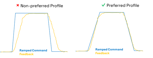
5. Motor tuning tips:
When selecting the motor acceleration and deceleration profile, prefer a ramp that the motor can closely follow. This will lead to a more precise and controlled movement. Even if the actual speed response of the motor in both cases is the same, the motor will react better in command changes and disturbances if it can closely follow the ramped command.
6. Troubleshooting

← 3.2.1 DC - Closed Loop - Torque v 1.0
3.2.3 DC - Closed Loop - Count Position v 1.0 →
3.2.4 DC- Closed Loop - Position Relative v 1.0 →