← 3.1.1 DC- Open Loop v 1.0 3.2.2 DC- Speed Mode v 1.0 →
Note: The Guide can be downloaded in PDF format at the end of the article.
Disclaimer and Safety Information
Disclaimer
This quick startup guide is provided as a complementary resource to the official motor drive manual and datasheets. It is not intended to be the sole source of information for proper motor drive configuration and operation. Incorrect configuration or software bugs may cause unintended behavior, including uncontrolled motor operation or runaway. Users must always conduct tests cautiously and ensure they have a reliable method to safely stop the system in such scenarios. Roboteq, the author, and related parties are not liable for any hardware damage, personal injury, or other consequences arising from the use or misuse of the information in this guide.
Safety Symbols Explanation

Table of Contents
1. How to Use This Guide
- This guide is part of a series of documents that must be followed sequentially to configure and test a Brushless DC motor. The process begins with the Open Loop configuration and continues through the sequence of documents until reaching the final target operating mode.
- For example, configuring a higher-level operating mode, such as Count Position with Hall sensors, requires completing the configuration and testing of lower-level modes, including Open, Torque and Speed modes.

2. Theory: Torque Mode Overview
- Dc Motors have a fixed field set by permanent magnets or fixed windings. The stator field angle cannot be adjusted; therefore, the motor's torque is directly proportional to the supplied current.
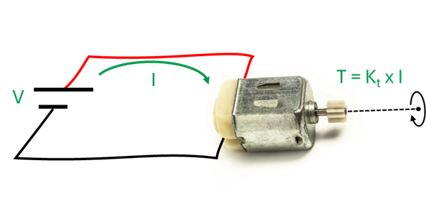
- The motor drive has integrated current sensors on the motor phases that are used to control the motor current using a Closed PI Loop.

- The motor can be controlled to achieve a desired torque value or a desired current value by sending the TC or G command, respectively. With the TC command, the drive calculates the required current to achieve the desired torque, based on the motor's torque constant (Kt). With the G command, the desired current is scaled from -1000 to 1000, where ±1000 corresponds to the current limit value stored in the Amps Limits parameter.
2. Theory: Cascaded Control Operation
- The motor drive uses a cascaded control structure: the Position Loop controls the Speed Loop, which controls the Torque Loop, ensuring stable motor control.
- Tuning Position mode requires both Speed and Torque loops to be tuned, while Speed mode needs only the Torque loop. Torque and Open Loop modes operate independently.
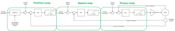

* Speed Loop is used in Torque mode for Speed Limiting
2. Theory: Torque Loop Tuning
The PI gains of the Torque PI Loop can be set by referring to the motor’s Resistance (R) and Inductance (L) parameters, using the zero-pole calculation method. The formula for this methos is as follows:
Torque I gain = Motor phase Resistance * 2 *pi * Bandwidth
Torque P gain = Motor phase Inductance * 2 *pi * Bandwidth
Resistance and inductance values can be obtained from the motor datasheet. The bandwidth can be set by the user based on the desired response. Roborun+ features a tool that facilitates with the Torque gains calculation. If the datasheet are not readily available, Torque mode can be tuned manually, as described in the following slides of this presentation

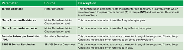
3. Required Parameters List
To complete the configuration sequence, ensure you have the following specifications readily available:
4. Configuration Steps
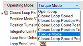
1. Set the Operating mode to ‘Torque Mode’.
2. Configure the motor’s constant (Kt) in Nm/A.
The torque constant parameter enables torque-based control, allowing you to send a torque request instead of a current command. The motor drive then translates the desired torque to the required current using the torque constant.

3. Set the motor’s resistance and inductance parameters.
These parameters are used to automatically calculate the torque gains using the zero-pole cancellation method, when running the “Motor Sensor and Tuning Setup” wizard. The motor's RL specifications are typically found in the motor datasheet. Ensure that you set Resistance values in Ohm and Inductance values in mH. If the motor specifications are unknown, the torque loop can be tuned experimentally, as described in the next steps.

4. Run the Motor Sensor and Tuning Setup Wizard
Motor Sensor and Tuning Setup wizard allows the calculation of The Torque gains, based on the configured motor RL specifications. The torque gains will be set according to the selected bandwidth. Prefer a bandwidth value from the Moderate range. Choosing bandwidth values that fall in the aggressive range will make the motor more responsive but may cause vibrations. Conversely, choosing conservative values can make the motor response sluggish.

5. Set the desired values for the current trajectory.
These values are configured through the Acceleration and Deceleration parameters. While in Speed mode, these parameters define the desired motion profile, with units in RPM/s, in Torque mode, they represent the desired rate of current change, expressed in mA*10/s.

6. Set the initial values for Speed PI gains.
Although the Torque loop does not rely on the Speed loop, the Speed loop is used to safely limit the motor speed to the maximum configured value. This is necessary in cases where the commanded torque cannot be achieved due to an inadequate motor load, which could otherwise cause the motor to run at its maximum possible speed. Motor speed limiting is accomplished through the Speed PI loop, so some PI gains are necessary for its operation. These PI gains can later be fine-tuned by monitoring the speed limiting process

7. Set the used sensor usage as feedback and select the channel.
Configuring a feedback sensor will enable the Speed limiting function that operates relying on the Speed PI Loop. The exact configuration steps have been described during Open Loop configuration guide.

Warning:
Before testing the motor in Closed Loop Torque mode, Open loop mode must be configured and evaluated, as incorrect sensor configuration can result in unintended and potentially dangerous motor behavior, such as uncontrolled movement.
Loading the motor might result in limitations related to the available space for movement. Two useful tools that can prevent the motor from reaching the space limits are the Watchdog timer and the Console commands.
In contrast to the slider, which sends continuously motor commands to the controller over a specific time period, console commands can be used to send the motor command only once.
![]()
Console commands, in combination with the Watchdog timer, can be used to stop the motor after a specific amount of time. The watchdog will stop the motor if the command is not renewed within a defined time period.
Sending the commands through the console guarantees that the watchdog timer will expire after the configured time.
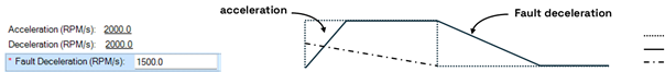
Watchdog timer will stop the motor using the configured Fault Deceleration parameter, so ensure that it has been set with the desired value:
A motor command in Torque Mode can be sent with the following syntax:
!G cc nn
where cc is the channel and nn is the desired current expressed in one-thousandths of the peak current configured in the Amps Limit parameter.
For example, the !G 1 500 command will request a current of 30 A for channel 1, given that Amps limit is configured to 60 A.
There is also the option to send a simultaneous motor command to both channels by combining the two commands with an underscore (“_”).
For example, the !G 1 250_!G 2 250 command will request a current of 15 A for both channels, given that Amps Limits in configured to 60 A.
Issuing a motor command for both motors can be useful in dual-channel applications like differential drive AGVs.
8. Navigate to the ‘Run’ tab and test motor response.
Issue a motor command either by using the slider or with the G runtime command. Both slider and G command set a current demand from 0 to 1000, where 1000 corresponds to the maximum motor current configured in the Amps Limits parameter. By monitoring the required variables through the run tab chart, ensure the following:
- The Moror Amps follows the Ramped Command.
- If the motor is not adequately loaded, then the requested current may not be reached. The motor speed will be increased to reach the requested current.
- In this case, ensure that the motor speed is limited to the Maximum Speed value.
- If the motor speed is not limited, or the speed correction is slow, increase the Speed PI gains.
- Add some load to the motor
- If the current response is slow, increase both Torque PI gains by the same value
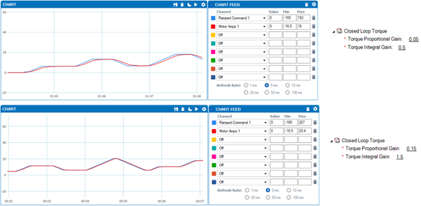
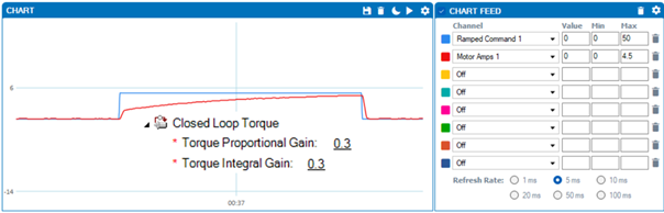
The following images illustrate the difference in the current response based on the configured Torque PI gain:
9. Manual Tuning of the Torque PI Gains (Only if motor RL specifications are unknown):
9.1. Temporarily disable trajectory ramp:
This will disable the current trajectory that is set through the Acceleration/Deceleration parameters, allowing a step input that will enable evaluation of the current response.

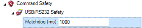
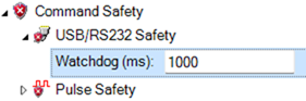
9.2. Configure the Watchdog timer to 1000 ms:
The Watchdog Timer is a safety feature that monitors the motor command input. If a new motor command is not received within the configured time period (in this case, 1000 ms), the timer will automatically reset the motor command to zero. This allows for a single motor command to be sent, eliminating the need for a subsequent command to reset the current demand to zero.
9.3. Set some small values to the Torque PI gains:
Start by setting some relatively small values such as P = I = 0.3.

9.4. Send a small current command with G command.
When the trajectory ramp is disabled, the current command must not exceed 10% of the motor's peak current, otherwise there is a risk of damaging the motor or drive. In the following example, we send a 50 motor command that equals 5% of the motor's configured peak current.

9.5. Adjust the Torque PI gains.
The goal is to achieve a smooth current response with a waveform shape similar to a first-order system open-loop step response. To accomplish this, increase the P gain to make the response faster, but be cautious that overly fast responses may lead to vibrations. Additionally, increase the I gain to minimize steady-state error. When tuning the PI gains, balance between response speed and stability, as a fast current response can cause vibrations, while a slow response may result in a sluggish motor.

The following images present the current step response with different Torque PI gains.
- In this example, the initial P gain (0.3) provides sufficient starting power, and the I gain is the only term that needs to be adjusted. By increasing the I gain by a factor of 10, the current response achieves the desired shape
- Once the desired waveform is achieved, both P and I gains can be multiplied by the same factor (e.g., 1, 2, 3, etc.) to make the response faster while maintaining its stable characteristics.
- In this example, P = 0.3 and I = 3.0 provide adequate results for an application that does not require an ultra-fast response.

9.6. Disable Bypass Trajectory Ramp.
The bypass trajectory setting, which was previously enabled for the sake of current tuning, must now be disabled again. Neglecting to disable this setting may result in the development of high currents, which can be harmful to the motor or drive

5. Troubleshooting
Below is a list of common issues that may arise when configuring Torque Mode:
- Motor does not start or stops after some time: Ensure that the watchdog timer is disabled or the motor command is sent repeatedly (e.g., through the slider)
- Motor reaches maximum speed when giving small command: When unloaded, the motor may accelerate to maximum speed while attempting to produce the required torque. To prevent this, set the motor's maximum speed limit within safe parameters. If over speeding persists despite this setting:
- Verify proper tuning of the Speed PID gains. For unloaded motors, typical effective values are P = I = 0.03 or P = I = 0.1 in some cases.
- Ensure that the motor sensor is properly configured as described in the Open Loop configuration guide
- Current response is slow: In torque mode, the motor current increases based on the acceleration and deceleration values, as well as the selected bandwidth. Even if the current bandwidth is high, the motor current cannot exceed the current trajectory. If a faster response is required, consider increasing the acceleration/deceleration values. The current trajectory can be monitored through the ramped command parameter.
- Motor Current/Target Value Mismatch: This discrepancy can occur due to several factors. Most commonly, the motor may lack sufficient load to generate the required torque. Another frequent cause involves misinterpretation between command and reported values. The table below provides clarification:
![]()