Note: The Guide can be downloaded in PDF format at the end of the article.
Disclaimer and Safety Information
Disclaimer
This quick startup guide is provided as a complementary resource to the official motor drive manual and datasheets. It is not intended to be the sole source of information for proper motor drive configuration and operation. Incorrect configuration or software bugs may cause unintended behavior, including uncontrolled motor operation or runaway. Users must always conduct tests cautiously and ensure they have a reliable method to safely stop the system in such scenarios. Roboteq, the author, and related parties are not liable for any hardware damage, personal injury, or other consequences arising from the use or misuse of the information in this guide.
Safety Symbols Explanation
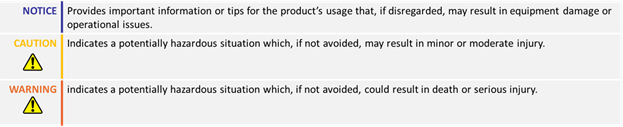
Table of Contents
1. How to Use This Guide
- This guide is part of a series of documents that must be followed sequentially to configure and test a Brushless DC motor. The process begins with the Open Loop configuration and continues through the sequence of documents until reaching the final target operating mode.
- For example, configuring a higher-level operating mode, such as Count Position with Hall sensors, requires completing the configuration and testing of lower-level modes, including Open, Torque and Speed modes.

2. Theory: Open Loop Mode Overview
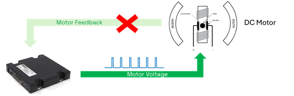
- Open Loop is the simplest operating mode, where the motor drive supplies a PWM voltage to the motor, without using a feedback sensor.
- In Open Loop mode, the motor commutation is achieved by using a commutator and brushes, so a rotor sensor is not required.
- Since there is no feedback sensor, the motor speed will vary depending on the applied load.
- While Open Loop is not the optimal operating mode, its configuration is a necessary step before proceeding with the configuration of the rest Closed Loop modes.
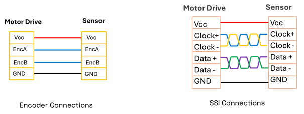
- Roboteq drives support Quadrature Encoders and SSI feedback sensors, which will be configured and tested during the Open Loop guide.
2. Theory: Cascaded Operation
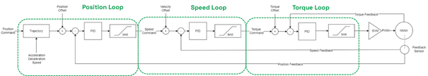
- The motor drive uses a cascaded control structure: the Position Loop controls the Speed Loop, which controls the Torque Loop, ensuring stable motor control.
- Tuning Position mode requires both Speed and Torque loops to be tuned, while Speed mode needs only the Torque loop. Torque and Open Loop modes operate independently.

3. Hardware Connections – Power Wires
- The drive can be powered from 12 to 60 V.
- Pwr ctrl supply is optional and can be used to keep the drive operational in case of main battery disconnection. However, Pwr ctrl must be connected to battery’s negative terminal to properly turn off the drive.
- Motor uses two wires for the supplied voltage. Swapping the two wires will reverse the direction of rotation
- Refer to the motor drive’s datasheet for the detailed connection diagram

Feedback Sensors
- Encoder sensors for channels 1 and 2 are typically connected to the Molex connector, while Encoder 3 is connected to the DB connector
- SSI sensors are connected to the Molex connector
- Consult each drive’s datasheet for the exact pinout and the supported sensor specifications
4. Required Parameters List
To complete the configuration sequence, ensure you have the following specifications readily available:

5. Configuration Steps
1. Set the Operating mode to ‘Open Loop’.
This is a very basic operating mode for simple applications and is a prerequisite step for configuring the Closed Loop operating modes.

2. Set the desired motion profile.
In Open Loop configuration, where no sensors are used, the speed cannot be directly measured. The drive will attempt to control the motor by applying the desired acceleration and deceleration, ramping up the PWM voltage based on the configured maximum speed and the set acceleration and deceleration values.

3. Configure the Amps Limit parameter
The drive will prevent the motor current from exceeding the amp limit parameter by reducing the motor voltage. The amp limit value should be set equal to the peak current of the application.


Since the peak current of a motor is typically only allowed for a short duration, Roboteq drives offer the option to trigger an action if the motor current exceeds a specified value for a specific amount of time. This can be configured using the Amps Trigger parameter.

4. Configure the I2T protection
I2T function will measure the energy provided to the motor and start limiting the current if it exceeds the allowed value. To enable the I2T protection, the motor’s peak current should have been set through the amps limit parameter. Then configure the nominal current and the time that the peak current is allowed to be supplied

5. Configure the Feedback Sensor.
Open Loop operation does not require a sensor; however, this step is necessary if the final target is to use Closed Loop modes, including Torque mode with Speed limiting.
- If an encoder sensor is used, configure its PPR
- If an SSI sensor is used, configure its resolution. The resolution number derives by calculating 2 to the power of number of bits (e.g. 4096 for 12 bits)
- Do not select an action for the used sensor, as this step will be performed during closed loop configuration

6. Move to the Run tab and test the motor in Open Loop.
Since the mode is Open Loop, the motor speed cannot be controlled and will vary depending on the load. In the Run tab enable the required variables and ensure the following:
- The motor rotates in both directions. If there is no high load applied, the motor speed should change by varying the motor command
- Ensure that the motor no load current is relatively low (typically between 10 to 30% of the rated current, assuming a small gear ratio)
- If a motor sensor is used, move the cursor to both ends and ensure that the expected speed (no-load maximum speed) is reached
- A very important step, if the intention is to later use any of the closed-loop modes, is to ensure that the motor speed is reported as positive when a positive command is given. If the speed is reported as negative, the encoder sensor resolution must be inverted (e.g., from 1024 to -1024 PPR)
