← 2.2.2 PMAC - Closed Loop - Speed v 1.0
← 2.2.3 PMAC - Speed Mode - Acceleration Feedforward control v1.0
Note: The Guide can be downloaded in PDF format at the end of the article.
Disclaimer and Safety Information
Disclaimer
This quick startup guide is provided as a complementary resource to the official motor drive manual and datasheets. It is not intended to be the sole source of information for proper motor drive configuration and operation. Incorrect configuration or software bugs may cause unintended behavior, including uncontrolled motor operation or runaway. Users must always conduct tests cautiously and ensure they have a reliable method to safely stop the system in such scenarios. Roboteq, the author, and related parties are not liable for any hardware damage, personal injury, or other consequences arising from the use or misuse of the information in this guide.
Safety Symbols Explanation
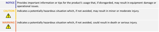
Table of Contents
- How to Use This Guide
- Theory
- Configuration Steps
- Closed Loop Speed Position Tuning
- Velocity Feedforward Tuning
- Troubleshooting
1. How to Use This Guide
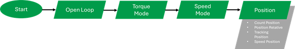
- This guide is part of a series of documents that must be followed sequentially to configure and test a PMAC motor. The process begins with the Open Loop configuration and continues through the sequence of documents until reaching the final target operating mode.
- For example, configuring a higher-level operating mode, such as Count Position with Hall sensors, requires completing the configuration and testing of lower-level modes, including Open, Torque and Speed modes.
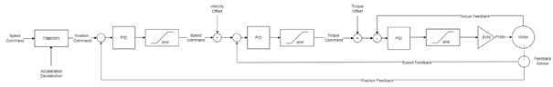
2. Theory: Cascaded Operation
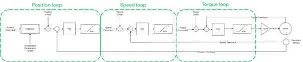
- The motor drive operates using a cascaded control structure. the Position Loop drives the Speed Loop, which in turn drives the Torque Loop, ensuring stable and efficient motor control.
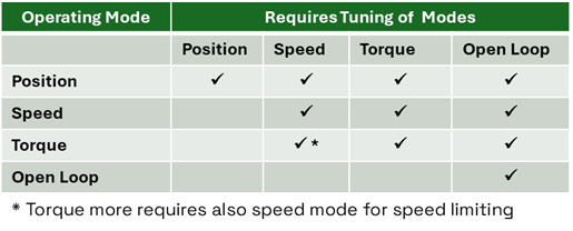
- Proper configuration and tuning of all internal modes is essential for optimal performance.
2. Theory: Mode Operation
- In this mode, the desired speed is converted into a target position for the motor at each millisecond. The PID controller then drives the motor using speed and torque loops to ensure it follows the target position accurately.
- Upon receiving the speed command, a trajectory is generated based on the acceleration and deceleration values. The target position is continuously updated according to the user command and motion profile, ensuring the motor follows the desired speed.
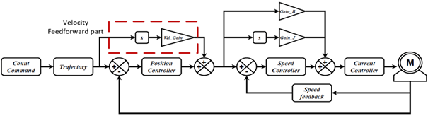
2. Theory: Velocity Feedforward control
- Velocity Feedforward control is an additional feedforward loop taking part in Position mode.
- In contrast to the Acceleration Feedforward control that acts in Speed Loop only during the acceleration of the motor, the Velocity Feedforward control acts every time there is a change in the trajectory and thus a motor movement.
- The controller operates by multiplying the motor's desired velocity by the velocity feedforward gain. The higher the velocity, the more feedforward power will be applied to the motor. The velocity feedforward power is added to the power output of the Position mode PID, so this mode operates in parallel to the position mode PID.
3. Configuration Steps
1. Set the operating mode to ‘Closed Loop Speed Position’
Closed-Loop Speed Position mode uses a predefined acceleration, constant velocity, and deceleration so it can move the motor a precise number of counts

2. Configure the feedback sensor
The feedback sensor should have already been configured through the Speed mode configuration step. Speed Position mode for BLDC drives supports Hall sensors, Incremental encoders, SSI sensors, Sin/Cos Sensors and Resolvers as feedback.

*Refer to the Open Loop and Speed mode sensor configuration sections
3. Configure the Closed Loop Error Detection
This parameter is used to detect large tracking errors due to mechanical or sensor failures and shut down the motor in case of problem in closed loop speed or position modes. The detection mechanism looks for the size of the tracking error and the duration the error is present. Both loop error limit at time parameters are configurable.
Be aware that in Speed Position mode, the Loop Error will be measured in counts and not RPM.

4. Set the desired motion profile
The motor will move to the desired position following a trapezoidal acceleration, speed, and deceleration profile. How closely this profile is followed is determined by the PID gains. Configure the acceleration, deceleration, and Max Speed parameters. Note that higher acceleration and deceleration values will require more current for the movements.


5. Set a starting value for the position proportional gain and start the tuning.
Speed Position mode uses the Position PID. Similar to Position mode, Speed Position mode, is primarily tuned using proportional gain. A small value, such as 0.03, can be tested initially. Increase the gain until the feedback matches the track command. Integral gain may reduce the final position error but can also cause overshoots. Test with a small amount of integral gain.

Warning:
Before testing closed-loop Speed Position, Open Loop and Speed modes must be configured, and the sensor must be set correctly so that the reported speed is positive when a positive command is given. If the sensor is not set properly, the motor may enter a dangerous runaway condition. Ensure you have followed the respective guides.
The Speed command can be sent either from the slider, or with the !S cc nn command, where cc is the channel and nn the requested speed in RPM.
For example, the !s 1 100 will instruct the motor to reach target speed of 100 rpm
By using serial commands and enabling the watchdog timer, the drive can safely stop the motor when the watchdog timer has expired. Be aware that the watchdog timer will not expire if the command is sent repeatedly e.g. by using the slider.

4. Closed Loop Count Position Tuning
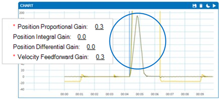
- Below are different sets of PI gains and their corresponding motor responses. It is evident that increasing the proportional gain results in a faster motor response.

5. Velocity Feedforward Tuning
6. Add some Velocity Feedforward Gain.
The Velocity Feedforward control can be enabled by adding a non-zero value to the Velocity Feedforward gain.
An easy way to determine the responsiveness of the position mode is to monitor the Loop Error. Increase the Velocity Feedforward gain, until the loop Error is minimized.

The negative Loop Error denotes an overshoot, so the Velocity Feedforward gain value that we will keep in this example is 1, which gives a small overshoot, accelerating the speed response.

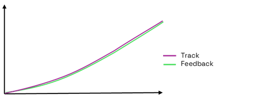
- After plotting the Track and Feedback values, the response of a well-tuned system should resemble the following:

6. Troubleshooting
Speed Position mode operation should be an easy and straightforward process. If the motor does not behave as expected, consider checking the following general points:
- Test the speed , Track command and Feedback
Send !s command along with the desired position to the Run Tab and verify that the feedback follows the track without delays and performs as expected.
- Ensure that Torque and Speed modes are properly configured and tuned.
The motor drive uses a cascaded control operation, where control modes are interdependent. Poor configuration of Torque or Speed modes can affect Position mode.
- PI Tuning.
Large amounts of P gain can cause vibrations. If the motor cannot reach the setpoint using only P gain, a small amount of I gain can be tested.
- Motor Runaway
This could be due to misconfiguration of the sensor (feedback changes in the opposite direction). Refer to the configuration guides of Open Loop, Torque and Speed modes to ensure that everything is set up properly.
- Slow response
The motor will follow the trajectory based on the PID settings. Achieving a faster response will require more current for the movement. However, if the current reaches the amp limit parameter, the response time cannot be further improved.
- Plotting advice
In Speed Position mode, both the input and feedback are measured in counts. As the motor rotates, the count values continuously increase, making it difficult to evaluate the position response when plotted. Instead, logging and plotting the Velocity Demand Value (VDV) and motor speed provide a clearer representation of the motor's performance.
← 2.2.2 PMAC - Closed Loop - Speed v 1.0
← 2.2.3 PMAC - Speed Mode - Acceleration Feedforward control v1.0