← 2.2.2 PMAC - Closed Loop - Speed v 1.0
← 2.2.3 PMAC - Speed Mode - Acceleration Feedforward control v1.0
Note: The Guide can be downloaded in PDF format at the end of the article.
Disclaimer and Safety Information
Disclaimer
This quick startup guide is provided as a complementary resource to the official motor drive manual and datasheets. It is not intended to be the sole source of information for proper motor drive configuration and operation. Incorrect configuration or software bugs may cause unintended behavior, including uncontrolled motor operation or runaway. Users must always conduct tests cautiously and ensure they have a reliable method to safely stop the system in such scenarios. Roboteq, the author, and related parties are not liable for any hardware damage, personal injury, or other consequences arising from the use or misuse of the information in this guide.
Safety Symbols Explanation

Table of Contents
- How to Use This Guide
- Theory
- Configuration Steps
- Closed Loop Count Position Tuning
- Velocity Feedforward Tuning
- Troubleshooting
1. How to Use This Guide
- This guide is part of a series of documents that must be followed sequentially to configure and test a PMAC motor. The process begins with the Open Loop configuration and continues through the sequence of documents until reaching the final target operating mode.
- For example, configuring a higher-level operating mode, such as Count Position with Hall sensors, requires completing the configuration and testing of lower-level modes, including Open, Torque and Speed modes.

2. Theory: Cascaded Operation
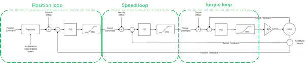
- The motor drive operates using a cascaded control structure. the Position Loop drives the Speed Loop, which in turn drives the Torque Loop, ensuring stable and efficient motor control.
- Proper configuration and tuning of all internal modes is essential for optimal performance.

2. Theory: Count Position Operation
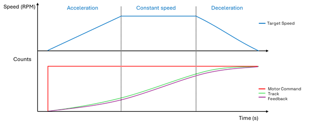
- In the Closed Loop Position mode, the drive will move the motor precisely for the desired number of counts, using a predefined acceleration, constant velocity, and deceleration.
- Upon receiving the user command, the pre-defined trajectory is applied, resulting in a smooth and controlled motion.
2. Theory: Motor Command and Feedback
- The Motor Command is the desired number of encoder sensor counts that the motor should move. The Position command can be received from various supported communication modes, such as USB, RS232, RS485, Ethernet, Modbus, CANbus etc.
- Various Feedback sensors are supported, such as Quadrature encoders, SSI sensors, Hall sensors, Sin/Cos and Resolvers.

- The Loop Error in Count Position mode is the difference between the Trajectory and the Feedback. Sensors having higher resolution will generate a larger Loop Error which in turn will result in a greater amount of motor power in the output of the Position mode PID.

- Hall sensors have a resolution equal to the number of motor pole pairs multiplied by 6
- Sin/Cos and Resolver sensors have a default resolution of 512 counts, as their minimum and maximum values are mapped to a range of 0 to 511.
2. Theory: Velocity Feedforward control
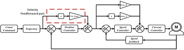
- Velocity Feedforward control is an additional feedforward loop taking part in Position mode.
- In contrast to the Acceleration Feedforward control that acts in Speed Loop only during the acceleration of the motor, the Velocity Feedforward control acts every time there is a change in the trajectory and thus a motor movement.
- The controller operates by multiplying the motor's desired velocity by the velocity feedforward gain. The higher the velocity, the more feedforward power will be applied to the motor. The velocity feedforward power is added to the power output of the Position mode PID, so this mode operates in parallel to the position mode PID.
3. Configuration Steps
1. Set the operating mode to ‘Closed Loop Count Position’
Closed-Loop Count Position mode uses a predefined acceleration, constant velocity, and deceleration to move the motor for the desired number of counts.

2. Configure the feedback sensor
The feedback sensor should have already been configured during Speed mode tuning.
- For Encoder or SSI sensors, set the sensor counts, channel and use and set the Closed Loop Feedback sensor to ‘Other’.
- For Hall, Sin/Cos or Resolvers, set the Closed Loop Feedback sensor to ‘Internal’ .

3. Configure the Closed Loop Error Detection
This parameter is used to detect large tracking errors due to mechanical or sensor failures and shut down the motor in case of problem in closed loop speed or position modes. The detection mechanism checks the size of the tracking error and the time the error is present. Both loop error limit and time parameters are configurable.

4. Set the desired motion profile
The motor will move to the desired position following a trapezoidal acceleration, speed, and deceleration profile. How closely this profile is followed is determined by the PID gains. Configure the acceleration, deceleration, and position mode velocity. Note that higher acceleration and deceleration values will require more current for the movements.


5. Set a starting value for the position proportional gain and start the tuning.
Position mode is primarily tuned using proportional gain. A small value, such as 0.03, can be tested initially. Increase the gain until the feedback matches the track command. Integral gain may reduce the final position error but can also cause overshoots. Test with a small amount of integral gain.

Warning:
Before testing closed-loop Position Relative, Open Loop and Speed modes must be configured, and the sensor must be set correctly so that the reported speed is positive when a positive command is given. If the sensor is not set properly, the motor may enter a dangerous runaway condition. Ensure you have followed the respective guides.
The motor command is sent with the !P cc nn and !PR cc nn commands
Example
- !P 1 5000 will move the motor of channel 1 to the absolute position of 5000 counts
- !PR 2 -500 will move the motor of channel 2, 500 counts away from the motor’s current position, in negative direction.

4. Closed Loop Count Position Tuning
- Next screenshots illustrate the motor response by using different sets of PI gains.

5. Velocity Feedforward Tuning
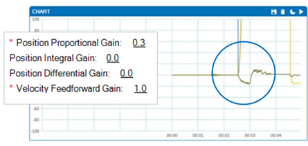
8. Add some Velocity Feedforward Gain.
The Velocity Feedforward control can be enabled by adding a non-zero value to the Velocity Feedforward gain.

An easy way to determine the responsiveness of the position mode is to monitor the Loop Error. Increase the Velocity Feedforward gain, until the loop Error is minimized.
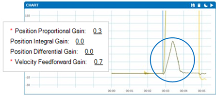
The negative Loop Error denotes an overshoot, so the Velocity Feedforward gain value that we will keep in this example is 1, which gives a small overshoot, accelerating the speed response.
- After plotting the Track and Feedback values, the response of a well-tuned system should resemble the following:

6. Troubleshooting
Count Position mode operation should be an easy and straightforward process. If the motor does not behave as expected, consider checking the following general points:
- Test the Position command and Feedback
Send !P command along with the desired position to the Run Tab and verify that the feedback follows the track without delays and performs as expected.
- Ensure that Torque and Speed modes are properly configured and tuned.
The motor drive uses a cascaded control operation, where control modes are interdependent. Poor configuration of Torque or Speed modes can affect Position mode.
- PI Tuning.
Large amounts of P gain can cause vibrations. If the motor cannot reach the setpoint using only P gain, a small amount of I gain can be tested.
- Motor Runaway
This could be due to misconfiguration of the sensor (feedback changes in the opposite direction).
- Slow response
The motor will follow the trajectory based on the PID settings. Achieving a faster response will require more current for the movement. However, if the current reaches the amp limit parameter, the response time cannot be further improved.
- Motor Does not Start:
Verify that the sensor is properly configured for feedback. Perform an emergency stop and manually rotate the shaft, ensuring that the feedback value changes. Monitor the chart to confirm that the motor command is received. Additionally, check the Run tab for any errors. If the motor command is received and no errors are present, then power should be supplied to the motor.
← 2.2.2 PMAC - Closed Loop - Speed v 1.0
← 2.2.3 PMAC - Speed Mode - Acceleration Feedforward control v1.0