← 2.2.2 PMAC - Closed Loop - Speed v 1.0
2.2.4 PMAC-Position Relative v 1.0 →
2.2.5 PMAC - Closed loop position tracking v 1.0 →
2.2.6 PMAC-Closed Loop Count Position v 1.0 →
2.2.7 PMAC-Closed Speed Position v 1.0 →
Note: The Guide can be downloaded in PDF format at the end of the article.
Disclaimer and Safety Information
Disclaimer
This quick startup guide is provided as a complementary resource to the official motor drive manual and datasheets. It is not intended to be the sole source of information for proper motor drive configuration and operation. Incorrect configuration or software bugs may cause unintended behavior, including uncontrolled motor operation or runaway. Users must always conduct tests cautiously and ensure they have a reliable method to safely stop the system in such scenarios. Roboteq, the author, and related parties are not liable for any hardware damage, personal injury, or other consequences arising from the use or misuse of the information in this guide.
Safety Symbols Explanation
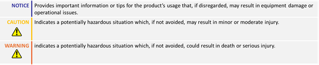
Table of Contents
- How to Use This Guide
- Theory
- Required Parameters List
- Configuration Steps
- Useful Command
- Tuning Steps
- Limitations and Considerations
- Troubleshooting
1. How to Use This Guide
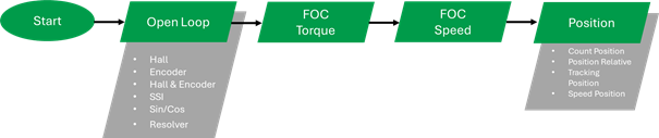
- This guide is part of a series of documents that must be followed sequentially to configure and test a PMAC motor. The process begins with the Open Loop configuration and continues through the sequence of documents until reaching the final target operating mode.
- The Open Loop mode guides are organized based on the sensor(s) used to commute the rotor (e.g., Hall, Hall & Encoder, Sin/Cos, etc.).
- According to this sequential structure, configuring a higher-level operating mode, such as Count Position with Hall sensors, requires completing the configuration and testing of lower-level modes, including Open Loop with Hall sensors, FOC Torque and FOC Speed.
- The Speed tuning of the motor consists of two portions: Closed Loop Speed PID tuning and acceleration Feedforward control tuning, which should be configured in a sequence. First, the Closed Loop Speed will be tuned, and then it can be optimized using the acceleration feedforward control. The feedforward control step is optional.

2. Theory: Acceleration Feedforward Control
- Acceleration Feedforward is a feedforward algorithm that operates mainly when the motor accelerates and decelerates.
- It takes the rate of change of the Speed command as an input - which corresponds to the desired acceleration - and then multiplies it by the system's inertia coefficient (J). This allows the algorithm to provide an additional amount of power during acceleration/deceleration to compensate for the load inertia.
- Additionally, there is a part that continuously multiplies the speed command with the motor’s rotating friction coefficient (B) to compensate for the friction losses.

- Acceleration Feedforward significantly enhances the motor's speed response during transients, where traditional PID control may fall short.

- Be aware that a slow motor response may not be solely due to motor control limitations. The response may be slow if there is insufficient power for the movement, which can occur when the motor drive reaches voltage or current limitations. Voltage limitation occurs when the provided voltage (motor power parameter) reaches its maximum value (+-1000), while current limitation occurs when the motor current reaches the configured Amps limit value. Before attempting to further improve the motor response, ensure that there is a sufficient power margin for this improvement by monitoring the motor power and motor amps parameters.
- The images below demonstrate the speed response with the same speed PID gains, both with and without acceleration feedforward enabled.
- Please note that the system is not yet fully fine-tuned, which is why there is a noticeable speed drop in the feedforward response.
No Feedforward control With Feedforward control

- Acceleration Feedforward control is enabled when both Inertia (J) and Rotating Friction (B) coefficients are set

- There are three ways to find the coefficients values:
- Using the Autotuning Wizard: The wizard will characterize the mechanical system by estimating its inertia and rotating friction coefficient. This information will be used to automatically calculate the required speed PID gains and enable Acceleration Feedforward control, once set.
- Experimentally: The J and B parameters can be manually adjusted to achieve the desired response. This will potentially require a few iterations of trial and error.
- Through Calculation: The coefficients can be calculated using the motor torque equations.
In this training, both experimental and calculation methods will be demonstrated. The Autotuning Wizard is a straightforward process that is demonstrated in dedicated training sessions.
Please note that before proceeding with the feedforward control configuration, the Closed Loop Speed mode must be already configured and tuned.
3. Required Parameters List
To complete the configuration sequence, ensure you have the following specifications readily available:

4.1 Configuration: Experimental Method
The steps to set the Acceleration feedforward gains follow:
1. Set both coefficients to 1
On this approach, we will primarily focus on the inertia component of the feedforward control, but both coefficients must have non-zero values for the feedforward control to be enabled.

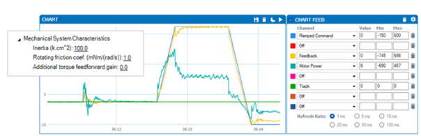
2. Increase the inertia coefficient up to the point that the transient response is improved
In these settings, the inertia coefficient has been increased to 100. By observing the motor power and feedback parameters, it is can be noticed how the motor speed and power drop when the motor is not accelerating and the acceleration part of the feedforward control is off.
4.2 Configuration: Calculation Method
The feedforward control aims to provide the amount of torque required for the movement of the system by utilizing the system’s model. The required torque to move the system with a specific acceleration and speed is given by the following equation:
?=????? ×?+???????????? ×?,
where B is the friction coefficient and J is the rotating inertia of the system.
These two coefficients can be estimated by taking the two below considerations:
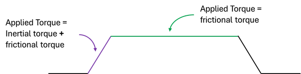
- The torque required to keep the system moving at a constant speed is equal to the system’s frictional torque
- The torque required to make the system accelerate at a specified acceleration is equal to the systems frictional torque plus the systems inertial torque
- The frictional torque, which opposes the motor’s movement due to friction and must be counteracted, can be calculated as:
?_?=?× Speed, where B is the friction coefficient of the system
- The inertial torque, which opposes the motor’s movement due to inertia and must be counteracted, can be calculated as:
?_?=?× Acceleration, where J is the inertia coefficient of the system
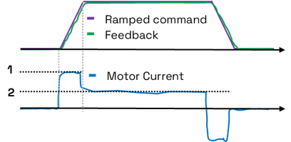
- If the system is well-tuned, the feedback should closely follow the ramped command. In that case, the acceleration and speed of the motor are known. By measuring the motor frictional and inertial torque and knowing the speed and acceleration parameters, the system’s inertia and friction coefficients can be calculated using the formulas above.
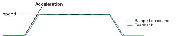
- The frictional and inertial torque, can be calculated from the motor current, given that the motor torque is equal to the motor current multiplied by the torque constant. As explained, the current consumed during the constant speed region will be proportional to the frictional torque, while the current consumed during acceleration will be proportional to both the inertial and frictional torques.
2) At constant state: ![]()
![]()
![]() B =
B = ![]()
Where:
Kt = Torque constant, As = motor current during steady state, Wn = rotational motor’s speed in rad/s
1) During acceleration:
![]()
Where:
Kt = Torque constant, Aacc = motor current during acceleration state, Wn = rotational motor’s speed in rad/s,
B = Calculated Friction coefficient, ![]() = motor’s rotational acceleration in rad/s2
= motor’s rotational acceleration in rad/s2
4.3 Configuration: Calculation Method Example
Rotating Friction Coefficient Calculation
- The motor should be configured and tuned in Closed Loop Speed mode, and its feedback should precisely follow the ramped command.
- A speed command should be issued, and the motor’s speed and current should be logged
- At steady state, find the mean value of the motor current.

At that point, we can consider that the effect of inertia on the system is minimal, and the only force at play is friction. In this scenario, the motor's torque becomes equivalent to its rotating friction coefficient multiplied by the angular frequency. Mathematically, this relationship is represented as:
![]()
By utilizing the motor's torque constant (Kt), we can substitute Torque with Kt x I:
![]()
Next, we convert the RPM to rad/s:
![]()
Solving for B, we arrive at the following formula:
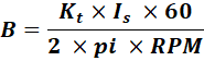
By considering a torque constant of 0.1 Nm/A and referring to the motor’s speed and current response, we can substitute the equation with the experimental values.
![]() =
= 

Inertia Coefficient Calculation
For the inertia coefficient, the motor current during acceleration should be determined.

When the motor accelerates, the applied torque becomes a sum of the motor acceleration multiplied by the inertia coefficient, and the motor speed multiplied by the rotating friction coefficient.
This relationship can be expressed as:

For the Rotating friction term, since the motor speed is not constant but accelerating, we can calculate the average speed of the motor and multiply it by the Rotating Friction coefficient:

The acceleration can be determined from the controller’s configuration. After transforming rad/s2 to RPM/s2 the formula becomes as follows:
![]() , where
, where ![]()
Substituting T with ?_?×?_??? gives:

By considering and acceleration of 2000 RPM/s2 we obtain the following results:
![]() =
= ![]()

![]()

5. Practice
- Exercise: Calculate the Rotating Friction coefficient of a loaded motor, tuned to follow a known speed profile (Acceleration – Constant Speed – Deceleration)
- Don’t neglect to multiply the results by 1000 as the controller units are mNm/(Rad/s)
- Exercise: Calculate the Inertia Coefficient of a loaded motor, tuned to follow a known speed profile (Acceleration – Constant Speed – Deceleration)
r. Don’t neglect to multiply the results by 10000 as the controller units are mNm/(Rad/s)
← 2.2.2 PMAC - Closed Loop - Speed v 1.0
2.2.4 PMAC-Position Relative v 1.0 →
2.2.5 PMAC - Closed loop position tracking v 1.0 →
2.2.6 PMAC-Closed Loop Count Position v 1.0 →