← 2.1.1 BLDC - Open Loop - Hall v 1.0 2.2.2 BLDC - Closed Loop - Speed v 1.0 →
← 2.1.2 BLDC - Open Loop - Encoder v 1.0
← 2.1.3 BLDC - Open Loop - Hall and Encoder v 1.0
← 2.1.4 BLDC - Open Loop - SSI v 1.0
← 2.1.5 BLDC - Open Loop - Sine Cosine v 1.0
← 2.1.6 BLDC - Open Loop - Resolver v 1.0
Note: The Guide can be downloaded in PDF format at the end of the article.
Disclaimer and Safety Information
Disclaimer
This quick startup guide is provided as a complementary resource to the official motor drive manual and datasheets. It is not intended to be the sole source of information for proper motor drive configuration and operation. Incorrect configuration or software bugs may cause unintended behavior, including uncontrolled motor operation or runaway. Users must always conduct tests cautiously and ensure they have a reliable method to safely stop the system in such scenarios. Roboteq, the author, and related parties are not liable for any hardware damage, personal injury, or other consequences arising from the use or misuse of the information in this guide.
Safety Symbols Explanation
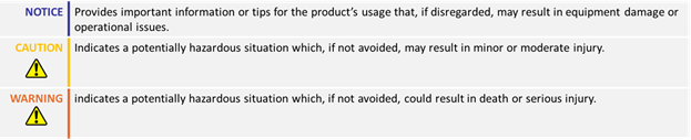
Table of Contents
How to Use This Guide
- This guide is part of a series of documents that must be followed sequentially to configure and test a BLDC motor. The process begins with the Open Loop configuration and continues through the sequence of documents until reaching the final target operating mode.
- The Open Loop mode guides are organized based on the sensor(s) used to commute the rotor (e.g., Hall, Hall & Encoder, Sin/Cos, etc.).
- According to this sequential structure, configuring a higher-level operating mode, such as Count Position with Hall sensors, requires completing the configuration and testing of lower-level modes, including Open Loop with Hall sensors, FOC Torque and FOC Speed.

Theory: Torque Loop
The Torque loop (also known as the FOC or Current Loop) is a PI loop responsible for controlling the motor current. Motor current comprises two components: one that imparts torque to the motor (Iq) and another that does not (Id).

The FOC loop aims to minimize the Id current and direct all useful current to the motor as Iq

Theory: Torque Loop
The FOC loop is the first mode that needs to be tuned before proceeding to the Speed or Position mode configurations. All three operating modes (Torque, Speed, and Position) work in a cascaded manner to effectively drive the motor.
Tuning the FOC loop is achieved by setting the FOC torque and Flux gains:

Theory: Torque Loop Tuning
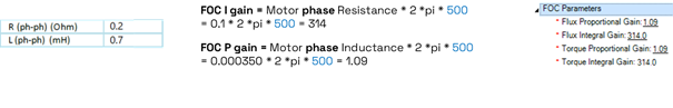
The FOC gains can be determined by referring to the motor's Resistance (R) and Inductance (L) parameters, following the formula below:
FOC I gain = Motor phase Resistance * 2 *pi * Bandwidth
FOC P gain = Motor phase Inductance * 2 *pi * Bandwidth
Resistance and inductance values can be obtained from the motor datasheet, or, as we will see subsequently, by using the motor characterization tool.

Theory: Torque Loop Tuning
- The Bandwidth of the Torque Loop is the only parameter that needs to be chosen by the user and sets the responsiveness of the FOC loop.
- Properly tuning the FOC loop will ensure that the current waveform accurately follows the set value with speed and stability.
50 Hz Bandwidth 500 Hz Bandwidth

Theory: Decoupling Control
- Decoupling current control is a feedforward loop that improves the current response of the motor. It operates by compensating for the cross-coupling between the torque and flux control loops, allowing for more precise control of the motor’s current and reducing the effects of load variations and parameter changes.
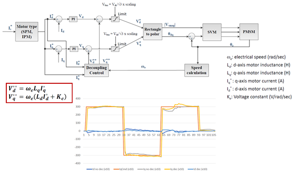
Theory: Decoupling Control Configuration
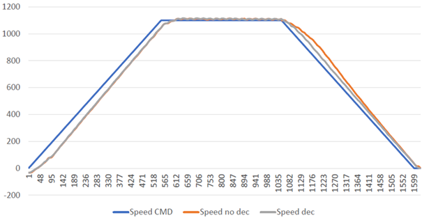
- The effects of decoupling control will become more evident in the motor's speed response, particularly during deceleration or during high-load transients.
- To enable Decoupling control, the voltage constant parameter must be set set along with the motor resistance and inductance specs. The voltage constant must be measured between two motor phases and expressed in RMS. The units should be V/kRPM.
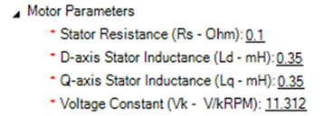
Required Parameters List
- To complete the configuration sequence, ensure you have the following specifications readily available:

Configuration Steps
To configure Torque mode, follow the next steps:
1. Set the FOC Torque and Flux gains.
These gains should have already been set during the Open Loop Configuration of the motor.
- If the datasheet have been used as a reference, ensure that the calculations are correct:
e.g. 500 Hz Bandwidth
- The calculations can be also performed from the Characterization wizard, by manually setting the RL values.
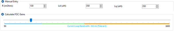
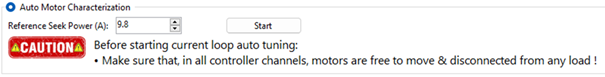
- If datasheet values are not available, use the motor characterization tool to estimate and calculate the FOC gains. Use a reference seek power value equal to the nominal current of the motor.
2. Evaluate the Current Response
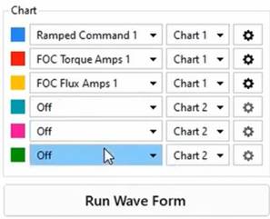
The current response of the motor can be monitored by using the tuning wizard. The wizard can provide the motor with a step command of configurable amplitude and frequency and plot the current response. In the wizard set the following:
Test waveform parameters:
- Amplitude: The min and max of the test waveform in Amps
- Time period: The period of the Test waveform in ms
- Repeat count: The number of periods of the waveform

Chart variables:
- Ramped command: The ramp of the provided current
- Torque Amps: The component of current that should follow the ramped command
- Flux amps: The component of current that should stay close to zero
- Try different values of FOC bandwidth and evaluate the current response by referring to the chart.
50 Hz Bandwidth 500 Hz Bandwidth

- Although higher bandwidth values make the current response faster, they also tend to introduce oscillations
- 500 Hz is a typical value for RoboG4.
3. Configure the Voltage Constant.
When the voltage constant is set along with the FOC gains, it enables decoupling control, which improves the current and speed response of the motor. Additionally, if the motor is of the IPM type, this parameter will enable special IPM control. The drive will automatically determine the motor type by referring to the FOC parameters.

4. Configure the Torque Constant.
This parameter is required if the torque command is given in Nm instead of amps. The firmware will convert the required torque into current using this parameter. Ensure that the parameter is measured in Nm/Arms.

5. Set the current Acceleration and Deceleration values.
In torque mode, these parameters set the ramp for the current command. The units are 10 mA/s. Lower acceleration and deceleration values will limit the current response, while higher values will make it more aggressive.

6. Set the Speed PID gains.
While torque mode does not require speed loop tuning, it relies on speed mode to perform functions such as speed limiting and quick stop. To allow these functions to be safely performed, some speed PID gains must be set. For more detailed speed mode tuning, refer to the dedicated tutorials.

7. Configure the Maximum motor speed.
The drive will not allow the motor speed to exceed this value, even if the torque command demands more power to be provided to the motor. As mentioned in the previous step, this function requires the speed PI gains to be set.
![]()
8. Test in Open Loop.
After the FOC response has been visualized, the motor should be tested in Open Loop, without load, to ensure that the FOC loop is effective in minimizing the Id current. To achieve that, follow the steps below:
- Provide full power in both directions (1000 and -1000 motor command) and ensure that the motor speed is symmetrical in both directions. If the FOC gains are not set properly, then the motor might not be able to reach the same speed in forward and reverse directions.
- Ensure that the FOC flux amps stay close to zero. Flux current might increase when the motor speed changes but it should stabilize back to 0 after a short time.
- Ensure that motor amps are below or equal to the motor’s no-load current.


9. Test the motor in Torque mode.
Put some load on the motor and ensure the following:
- Feedback is following the Ramped command
- Speed is effectively limited to the max speed parameter

Below are some considerations about setting and testing Torque mode:
- If there is not enough load in the motor and the current request cannot be reached, the speed of the motor will be increased to the maximum.
- If the speed gains are set, the motor speed will be limited to the Maximum configured Speed value.
- The given command from the slider is a !G command. The !G command will request a percentage of motor current between 0 and Amps limit value. For example, a !G command of 500 with an Amps limit value of 50 A, will request the 50% of 50 amps, that is 25 A.
- To request an absolute current value, the !GIQ command must be sent. The !GIQ command is a Torque Amps request.
- Torque amps are expressed in Peak value and not rms. Therefore, the measured motor Amps will be equal to Torque amps*0.707.
If the Feedback follows the Ramped command in a fast and stable manner, the Torque Loop is properly tuned!
Troubleshooting
Torque mode is easy to configure and tune. However, some common issues that may arise include:
- Current response is slow: In torque mode, the motor current increases based on the acceleration and deceleration values, as well as the selected bandwidth. Even if the current bandwidth is high, the motor current cannot exceed the current trajectory. If a faster response is required, consider increasing the acceleration/deceleration values. The current trajectory can be monitored through the ramped command parameter.

- Motor current does not match the target value: This may occur for several reasons. A common reason is that the motor is not sufficiently loaded to develop the desired torque. Another common reason could be a misunderstanding of the command and reported values. The following table aims to clarify this.
![]()
← 2.1.1 BLDC - Open Loop - Hall v 1.0 2.2.2 BLDC - Closed Loop - Speed v 1.0 →
← 2.1.2 BLDC - Open Loop - Encoder v 1.0
← 2.1.3 BLDC - Open Loop - Hall and Encoder v 1.0
← 2.1.4 BLDC - Open Loop - SSI v 1.0